Chapter 12—Transition to Multiengine Airplanes
Table of Contents
Multiengine Flight
General
Terms and Definitions
Operation of Systems
Propellers
Propeller Synchronization
Fuel Crossfeed
Combustion Heater
Flight Director / Autopilot
Yaw Damper
Alternator / Generator
Nose Baggage Compartment
Anti-Icing / Deicing
Performance and Limitations
Weight and Balance
Ground Operation
Normal and Crosswind Takeoff and Climb
Level Off and Cruise
Normal Approach and Landing
Crosswind Approach and Landing
Short-Field Takeoff and Climb
Short-Field Approach and Landing
Go-Around
Rejected Takeoff
Engine Failure After Lift-Off
Engine Failure During Flight
Engine Inoperative Approach Landing
Engine Inoperative Flight Principles
Slow Flight
Stalls
Power-Off Stalls (Approach and Landing)
Power-On Stalls (Takeoff and Departure)
Spin Awareness
Engine Inoperative—Loss of Directional Control Demonstration
Multiengine Training Considerations

ENGINE INOPERATIVE FLIGHT PRINCIPLES
Best single-engine climb performance is obtained at VYSE with maximum available power and minimum drag. After the flaps and landing gear have been retracted and the propeller of the failed engine feathered, a key element in best climb performance is minimizing sideslip.
With a single-engine airplane or a multiengine airplane with both engines operative, sideslip is eliminated when the ball of the turn and bank instrument is centered. This is a condition of zero sideslip, and the airplane is presenting its smallest possible profile to the relative wind. As a result, drag is at its minimum. Pilots know this as coordinated flight.
In a multiengine airplane with an inoperative engine, the centered ball is no longer the indicator of zero sideslip due to asymmetrical thrust. In fact, there is no instrument at all that will directly tell the pilot the flight conditions for zero sideslip. In the absence of a yaw string, minimizing sideslip is a matter of placing the airplane at a predetermined bank angle and ball position. The AFM/POH performance charts for single- engine flight were determined at zero sideslip. If this performance is even to be approximated, the zero sideslip technique must be utilized.
There are two different control inputs that can be used to counteract the asymmetrical thrust of a failed engine: (1) yaw from the rudder, and (2) the horizontal component of lift that results from bank with the ailerons. Used individually, neither is correct. Used together in the proper combination, zero sideslip and best climb performance are achieved.
Three different scenarios of airplane control inputs are presented below. Neither of the first two is correct. They are presented to illustrate the reasons for the zero sideslip approach to best climb performance.
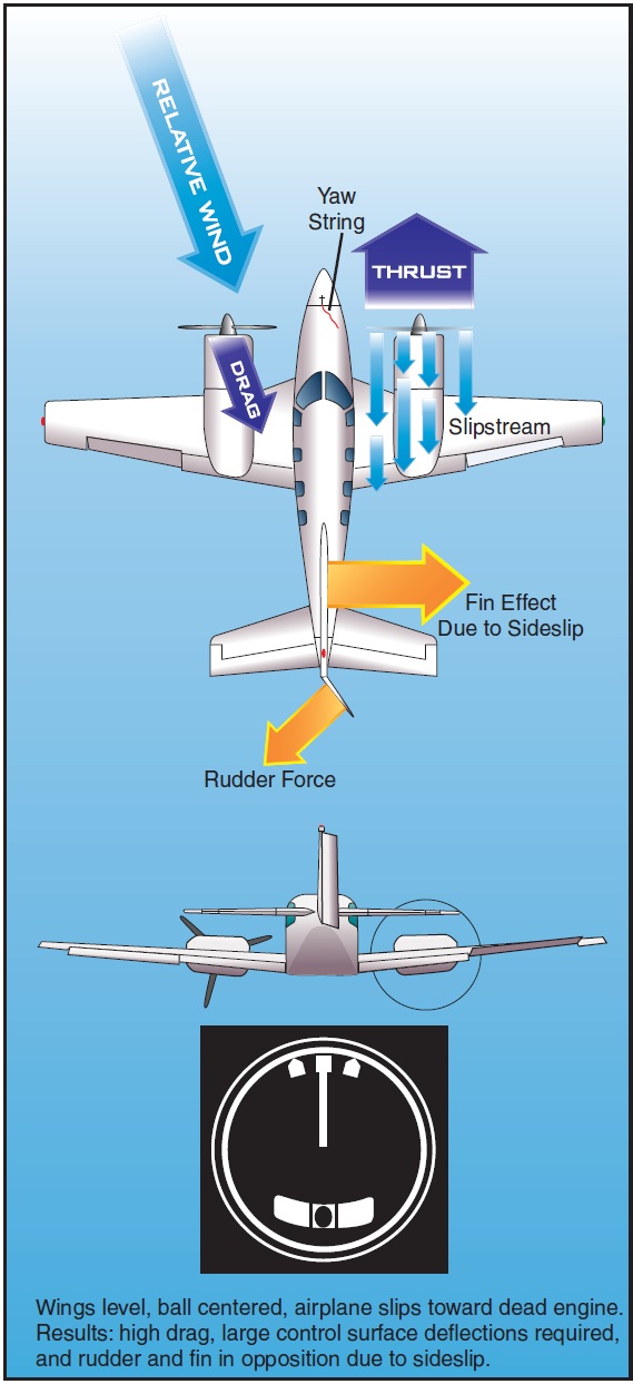
1. Engine inoperative flight with wings level and ball centered requires large rudder input towards the operative engine. [Figure 12-16] The result is a moderate sideslip towards the inoperative engine. Climb performance will be reduced by the moderate sideslip. With wings level, VMC will be significantly higher than published as there is no horizontal component of lift available to help the rudder combat asymmetrical thrust.

Figure 12-16. Wings level engine-out flight.
Ch 12.qxd 5/7/04 9:55 AM Page 12-24
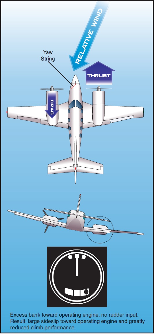
2. Engine inoperative flight using ailerons alone requires an 8 - 10° bank angle towards the operative engine. [Figure 12-17] This assumes no rudder input. The ball will be displaced well towards the operative engine. The result is a large sideslip towards the operative engine. Climb performance will be greatly reduced by the large sideslip.

Figure 12-17. Excessive bank engine-out flight.
3. Rudder and ailerons used together in the proper combination will result in a bank of approximately 2° towards the operative engine. The ball will be displaced approximately one-third to one-half towards the operative engine. The result is zero sideslip and maximum climb performance. [Figure 12-18] Any attitude other than zero sideslip increases drag, decreasing performance. VMC under these circumstances will be higher than published, as less than the 5° bank certification limit is employed.
12-24

Figure 12-18. Zero sideslip engine-out flight.
The precise condition of zero sideslip (bank angle and ball position) varies slightly from model to model, and with available power and airspeed. If the airplane is not equipped with counter-rotating propellers, it will also vary slightly with the engine failed due to P-factor. The foregoing zero sideslip recommendations apply to reciprocating engine multiengine airplanes flown at VYSE with the inoperative engine feathered. The zero sideslip ball position for straight flight is also the zero sideslip position for turning flight.
Ch 12.qxd 5/7/04 9:55 AM Page 12-25
When bank angle is plotted against climb performance for a hypothetical twin, zero sideslip results in the best (however marginal) climb performance or the least rate of descent. Zero bank (all rudder to counteract yaw) degrades climb performance as a result of moderate sideslip. Using bank angle alone (no rudder) severely degrades climb performance as a result of a large sideslip.
The actual bank angle for zero sideslip varies among airplanes from one and one-half to two and one-half degrees. The position of the ball varies from one-third to one-half of a ball width from instrument center.
For any multiengine airplane, zero sideslip can be confirmed through the use of a yaw string. A yaw string is a piece of string or yarn approximately 18 to 36 inches in length, taped to the base of the windshield, or to the nose near the windshield, along the airplane centerline. In two-engine coordinated flight, the relative wind will cause the string to align itself with the longitudinal axis of the airplane, and it will position itself straight up the center of the windshield. This is zero sideslip. Experimentation with slips and skids will vividly display the location of the relative wind. Adequate altitude and flying speed must be maintained while accomplishing these maneuvers.
With an engine set to zero thrust (or feathered) and the airplane slowed to VYSE, a climb with maximum power on the remaining engine will reveal the precise bank angle and ball deflection required for zero sideslip and best climb performance. Zero sideslip will again be indicated by the yaw string when it aligns itself vertically on the windshield. There will be very minor changes from this attitude depending upon the engine failed (with noncounter-rotating propellers), power available, airspeed and weight; but without more sensitive testing equipment, these changes are difficult to detect. The only significant difference would be the pitch attitude required to maintain VYSE under different density altitude, power available, and weight conditions.
If a yaw string is attached to the airplane at the time of a VMC demonstration, it will be noted that VMC occurs under conditions of sideslip. VMC was not determined under conditions of zero sideslip during aircraft certification and zero sideslip is not part of a VMC demonstration for pilot certification.
To review, there are two different sets of bank angles used in one-engine-inoperative flight.
- To maintain directional control of a multiengine airplane suffering an engine failure at low speeds (such as climb), momentarily bank at least 5°, and a maximum of 10° towards the operative engine as the pitch attitude for VYSE is set. This maneuver should be instinctive to the proficient multiengine pilot and take only 1 to 2 seconds to attain. It is held just long enough to assure directional control as the pitch attitude for VYSE is assumed.
- To obtain the best climb performance, the airplane must be flown at VYSE and zero sideslip, with the failed engine feathered and maximum available power from the operating engine. Zero sideslip is approximately 2° of bank toward the operating engine and a one-third to one-half ball deflection, also toward the operating engine. The precise bank angle and ball position will vary somewhat with make and model and power available. If above the airplane’s single-engine ceiling, this attitude and configuration will result in the minimum rate of sink.
In OEI flight at low altitudes and airspeeds such as the initial climb after takeoff, pilots must operate the airplane so as to guard against the three major accident factors:
- loss of directional control,
- loss of performance, and
- loss of flying speed.
All have equal potential to be lethal. Loss of flying speed will not be a factor, however, when the airplane is operated with due regard for directional control and performance.
PED Publication