Chapter 15-Transition to Jet Powered Airplanes
Table of Contents
General
Jet Engine Basics
Operating the Jet Engine
Jet Engine Ignition
Continuous Ignition
Fuel Heaters
Setting Power
Thrust to Thrust Lever Relationship
Variation of Thrust with RPM
Slow Acceleration of the Jet Engine
Jet Engine Efficiency
Absence of Propeller Effect
Absence of Propeller Slipstream
Absence of Propeller Drag
Speed Margins
Recovery from Overspeed Conditions
Mach Buffet Boundaries
Low Speed Flight
Stalls
Drag Devices
Thrust Reversers
Pilot Sensations in Jet Flying
Jet Airplane Takeoff and Climb
V-Speeds
Pre-Takeoff Procedures
Takeoff Roll
Rotation and Lift-Off
Initial Climb
Jet Airplane Approach and Landing
Landing Requirements
Landing Speeds
Significant Differences
The Stabilized Approach
Approach Speed
Glidepath Control
The Flare
Touchdown and Rollout

JET ENGINE IGNITION
Most jet engine ignition systems consist of two igniter plugs, which are used during the ground or air starting of the engine. Once the start is completed, this ignition either automatically goes off or is turned off, and from this point on, the combustion in the engine is a continuous process.
CONTINUOUS IGNITION
An engine is sensitive to the flow characteristics of the air that enters the intake of the engine nacelle. So long as the flow of air is substantially normal, the engine will continue to run smoothly. However, particularly with rear mounted engines that are sometimes in a position to be affected by disturbed airflow from the wings, there are some abnormal flight situations that could cause a compressor stall or flameout of the engine. These abnormal flight conditions would usually be associated with abrupt pitch changes such as might be encountered in severe turbulence or a stall.
In order to avoid the possibility of engine flameout from the above conditions, or from other conditions that might cause ingestion problems such as heavy rain, ice, or possible bird strike, most jet engines are equipped with a continuous ignition system. This system can be turned on and used continuously whenever the need arises. In many jets, as an added precaution, this system is normally used during takeoffs and landings. Many jets are also equipped with an automatic ignition system that operates both igniters whenever the airplane stall warning or stick shaker is activated.
FUEL HEATERS
Because of the high altitudes and extremely cold outside air temperatures in which the jet flies, it is possible to supercool the jet fuel to the point that the small particles of water suspended in the fuel can turn to ice crystals and clog the fuel filters leading to the engine. For this reason, jet engines are normally equipped with fuel heaters. The fuel heater may be of the automatic type which constantly maintains the fuel temperature above freezing, or they may be manually controlled by the pilot from the cockpit.
Ch 15.qxd 5/7/04 10:22 AM Page 15-4SETTING POWER
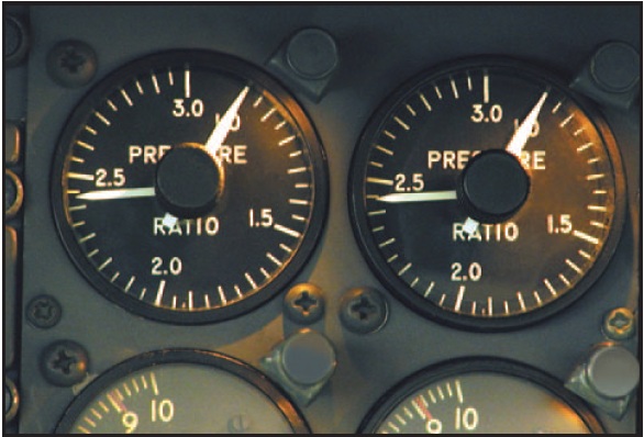
On some jet airplanes, thrust is indicated by an engine pressure ratio (EPR) gauge. Engine pressure ratio can be thought of as being equivalent to the manifold pressure on the piston engine. Engine pressure ratio is the difference between turbine discharge pressure and engine inlet pressure. It is an indication of what the engine has done with the raw air scooped in. For instance, an EPR setting of 2.24 means that the discharge pressure relative to the inlet pressure is 2.24 : 1. On these airplanes, the EPR gauge is the primary reference used to establish power settings. [Figure 15-5]

Figure 15-5. EPR gauge.
Fan speed (N1) is the primary indication of thrust on most turbofan engines. Fuel flow provides a secondary thrust indication, and cross-checking for proper fuel flow can help in spotting a faulty N1 gauge. Turbofans also have a gas generator turbine tachometer (N2). They are used mainly for engine starting and some system functions.
In setting power, it is usually the primary power reference (EPR or N1) that is most critical, and will be the gauge that will first limit the forward movement of the thrust levers. However, there are occasions where the limits of either r.p.m. or temperature can be exceeded. The rule is: movement of the thrust levers must be stopped and power set at whichever the limits of EPR, r.p.m., or temperature is reached first.
PED Publication