Chapter 15-Transition to Jet Powered Airplanes
Table of Contents
General
Jet Engine Basics
Operating the Jet Engine
Jet Engine Ignition
Continuous Ignition
Fuel Heaters
Setting Power
Thrust to Thrust Lever Relationship
Variation of Thrust with RPM
Slow Acceleration of the Jet Engine
Jet Engine Efficiency
Absence of Propeller Effect
Absence of Propeller Slipstream
Absence of Propeller Drag
Speed Margins
Recovery from Overspeed Conditions
Mach Buffet Boundaries
Low Speed Flight
Stalls
Drag Devices
Thrust Reversers
Pilot Sensations in Jet Flying
Jet Airplane Takeoff and Climb
V-Speeds
Pre-Takeoff Procedures
Takeoff Roll
Rotation and Lift-Off
Initial Climb
Jet Airplane Approach and Landing
Landing Requirements
Landing Speeds
Significant Differences
The Stabilized Approach
Approach Speed
Glidepath Control
The Flare
Touchdown and Rollout

OPERATING THE JET ENGINE
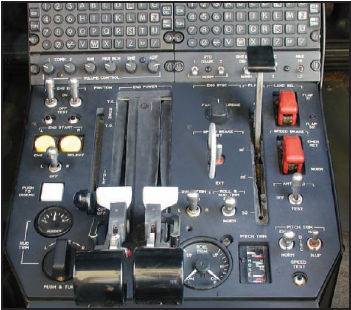
In a jet engine, thrust is determined by the amount of fuel injected into the combustion chamber. The power controls on most turbojet and turbofan powered airplanes consist of just one thrust lever for each engine, because most engine control functions are automatic. The thrust lever is linked to a fuel control and/or electronic engine computer that meters fuel flow based upon r.p.m., internal temperatures, ambient conditions, and other factors. [Figure 15-3]

Figure 15-3. Jet engine power controls.
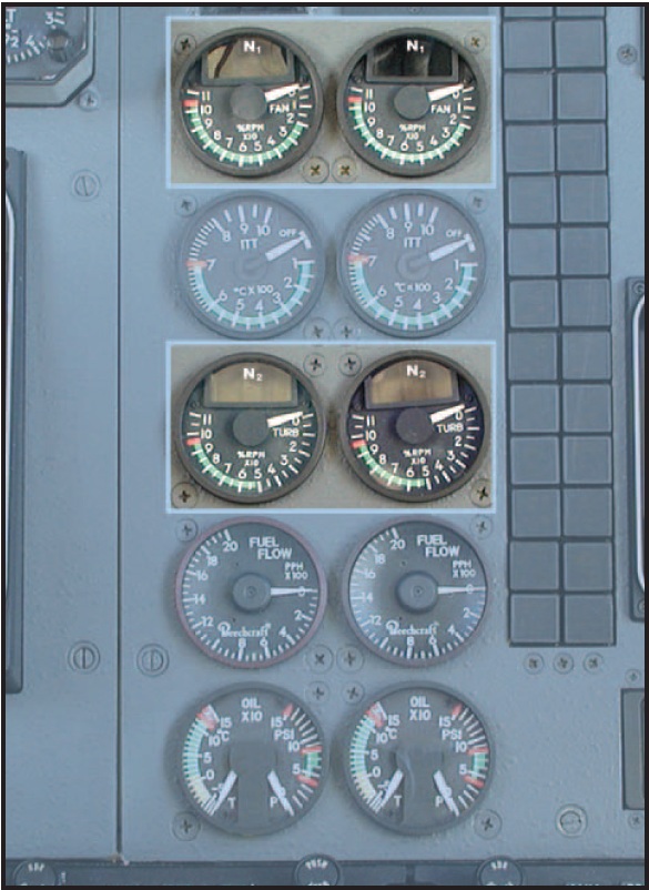
In a jet engine, each major rotating section usually has a separate gauge devoted to monitoring its speed of rotation. Depending on the make and model, a jet engine may have an N1 gauge that monitors the low pressure compressor section and/or fan speed in turbofan engines. The gas generator section may be monitored by an N2 gauge, while triple spool engines may have an N3 gauge as well. Each engine section rotates at many thousands of r.p.m. Their gauges therefore are calibrated in percent of r.p.m. rather than actual r.p.m., for ease of display and interpretation. [Figure 15-4]

Figure 15-4. Jet engine r.p.m. gauges.
The temperature of turbine gases must be closely monitored by the pilot. As in any gas turbine engine, exceeding temperature limits, even for a very few seconds, may result in serious heat damage to turbine blades and other components. Depending on the make and model, gas temperatures can be measured at a number of different locations within the engine. The associated engine gauges therefore have different names according to their location. For instance:
ò Exhaust Gas Temperature (EGT)ùthe temperature of the exhaust gases as they enter the tail pipe, after passing through the turbine. ò Turbine Inlet Temperature (TIT)ùthe temperature of the gases from the combustion section of the engine as they enter the first stage of the turbine. TIT is the highest temperature inside a gas turbine engine and is one of the limiting factors of the amount of power the engine can produce. TIT, however, is difficult to measure. EGT therefore, which relates to TIT, is normally the parameter measured. ò Interstage Turbine Temperature (ITT)ùthe temperature of the gases between the high pressure and low pressure turbine wheels. ò Turbine Outlet Temperature (TOT)ùlike EGT, turbine outlet temperature is taken aft of the turbine wheel(s).PED Publication