11—Transition to Complex Airplanes
Table of Contents
High Performance and Complex Airplanes
Wing Flaps
Function of Flaps
Flap Effectiveness
Operational Procedures
Controllable-Pitch Propeller
Constant-Speed Propeller
Takeoff, Climb, and Cruise
Blade Angle Control
Governing Range
Constant-Speed Propeller Operation
Turbocharging
Ground Boosting vs. Altitude Turbocharging
Operating Characteristics
Heat Management
Turbocharger Failure
Overboost Condition
Low Manifold Pressure
Retractable Landing Gear
Landing Gear Systems
Controls and Position Indicators
Landing Gear Safety Devices
Emergency Gear Extension Systems
Operational Procedures PreFlight
Takeoff and Climb
Approach and Landing
Transition Training

WING FLAPS
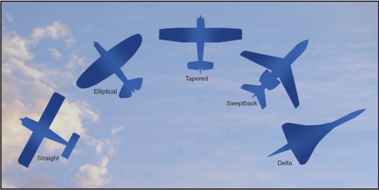
Airplanes can be designed to fly fast or slow. High speed requires thin, moderately cambered airfoils with a small wing area, whereas the high lift needed for low speeds is obtained with thicker highly cambered airfoils with a larger wing area. [Figure 11-1] Many attempts have been made to compromise this conflicting requirement of high cruise and slow landing speeds.

Figure 11-1. Airfoil types.
Since an airfoil cannot have two different cambers at the same time, one of two things must be done. Either the airfoil can be a compromise, or a cruise airfoil can be combined with a device for increasing the camber of the airfoil for low-speed flight. One method for varying an airfoil’s camber is the addition of trailing edge flaps. Engineers call these devices a high-lift system.
FUNCTION OF FLAPS
Flaps work primarily by changing the camber of the airfoil since deflection adds aft camber. Flap deflection does not increase the critical (stall) angle of attack, and in some cases flap deflection actually decreases the critical angle of attack.
Deflection of trailing edge control surfaces, such as the aileron, alters both lift and drag. With aileron deflection, there is asymmetrical lift (rolling moment) and drag (adverse yaw). Wing flaps differ in that deflection acts symmetrically on the airplane. There is no roll or yaw effect, and pitch changes depend on the airplane design.
Pitch behavior depends on flap type, wing position, and horizontal tail location. The increased camber from flap deflection produces lift primarily on the rear portion of the wing. This produces a nosedown pitching moment; however, the change in tail load from the downwash deflected by the flaps over the horizontal tail has a significant influence on the pitching moment. Consequently, pitch behavior depends on the design features of the particular airplane.
Flap deflection of up to 15° primarily produces lift with minimal drag. The tendency to balloon up with initial flap deflection is because of lift increase, but the nosedown pitching moment tends to offset the balloon. Deflection beyond 15° produces a large increase in drag. Drag from flap deflection is parasite drag, and as such is proportional to the square of the speed. Also, deflection beyond 15° produces a significant noseup pitching moment in most high-wing airplanes because the resulting downwash increases the airflow over the horizontal tail.
Ch 11.qxd 5/7/04 8:50 AM Page 11-2
FLAP EFFECTIVENESS
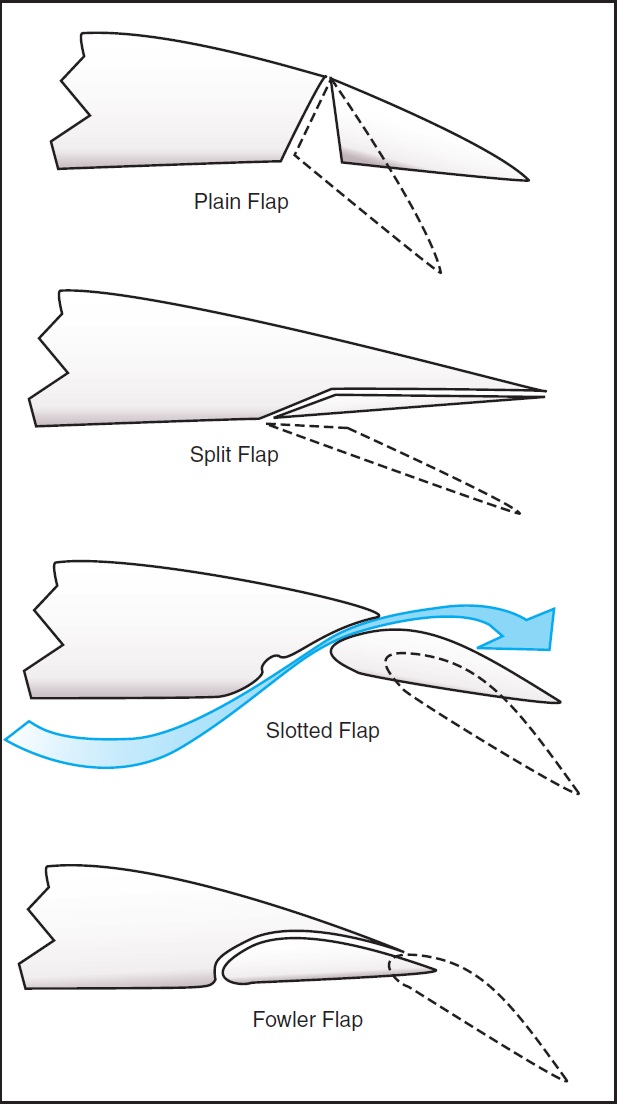
Flap effectiveness depends on a number of factors, but the most noticeable are size and type. For the purpose of this chapter, trailing edge flaps are classified as four basic types: plain (hinge), split, slotted, and Fowler. [Figure 11-2]

Figure 11-2. Four basic types of flaps.
The plain or hinge flap is a hinged section of the wing. The structure and function are comparable to the other control surfaces—ailerons, rudder, and elevator. The split flap is more complex. It is the lower or underside portion of the wing; deflection of the flap leaves the trailing edge of the wing undisturbed. It is, however, more effective than the hinge flap because of greater lift and less pitching moment, but there is more drag. Split flaps are more useful for landing, but the partially deflected hinge flaps have the advantage in takeoff. The split flap has significant drag at small deflections, whereas the hinge flap does not because airflow remains “attached” to the flap.
The slotted flap has a gap between the wing and the leading edge of the flap. The slot allows high pressure airflow on the wing undersurface to energize the lower pressure over the top, thereby delaying flow separation. The slotted flap has greater lift than the hinge flap but less than the split flap; but, because of a higher lift-drag ratio, it gives better takeoff and climb performance. Small deflections of the slotted flap give a higher drag than the hinge flap but less than the split. This allows the slotted flap to be used for takeoff.
The Fowler flap deflects down and aft to increase the wing area. This flap can be multi-slotted making it the most complex of the trailing edge systems. This system does, however, give the maximum lift coefficient. Drag characteristics at small deflections are much like the slotted flap. Because of structural complexity and difficulty in sealing the slots, Fowler flaps are most commonly used on larger airplanes.
OPERATIONAL PROCEDURES
It would be impossible to discuss all the many airplane design and flap combinations. This emphasizes the importance of the FAA-approved Airplane Flight Manual and/or Pilot’s Operating Handbook (AFM/POH) for a given airplane. However, while some AFM/POHs are specific as to operational use of flaps, many are lacking. Hence, flap operation makes pilot judgment of critical importance. In addition, flap operation is used for landings and takeoffs, during which the airplane is in close proximity to the ground where the margin for error is small.
Since the recommendations given in the AFM/POH are based on the airplane and the flap design combination, the pilot must relate the manufacturer’s recommendation to aerodynamic effects of flaps. This requires that the pilot have a basic background knowledge of flap aerodynamics and geometry. With this information, the pilot must make a decision as to the degree of flap deflection and time of deflection based on runway and approach conditions relative to the wind conditions.
The time of flap extension and degree of deflection are related. Large flap deflections at one single point in the landing pattern produce large lift changes that require significant pitch and power changes in order to maintain airspeed and glide slope. Incremental deflection of flaps on downwind, base, and final approach allow smaller adjustment of pitch and power compared to extension of full flaps all at one time. This procedure facilitates a more stabilized approach.
A soft- or short-field landing requires minimal speed at touchdown. The flap deflection that results in minimal groundspeed, therefore, should be used. If obstacle clearance is a factor, the flap deflection that results in the steepest angle of approach should be used. It should be noted, however, that the flap setting that gives the minimal speed at touchdown does not necessarily give the steepest angle of approach; however, maximum flap extension gives the steepest angle of approach and minimum speed at touchdown. Maximum flap extension, particularly beyond 30 to 35°, results in a large amount of drag. This requires higher power settings than used with partial flaps. Because of the steep approach angle combined with power to offset drag, the flare with full flaps becomes critical. The drag produces a high sink rate that must be controlled with power, yet failure to reduce power at a rate so that the power is idle at touchdown allows the airplane to float down the runway. A reduction in power too early results in a hard landing.
Crosswind component is another factor to be considered in the degree of flap extension. The deflected flap presents a surface area for the wind to act on. In a crosswind, the “flapped” wing on the upwind side is more affected than the downwind wing. This is, however, eliminated to a slight extent in the crabbed approach since the airplane is more nearly aligned with the wind. When using a wing low approach, however, the lowered wing partially blankets the upwind flap, but the dihedral of the wing combined with the flap and wind make lateral control more difficult. Lateral control becomes more difficult as flap extension reaches maximum and the crosswind becomes perpendicular to the runway.
Crosswind effects on the “flapped” wing become more pronounced as the airplane comes closer to the ground. The wing, flap, and ground form a “container” that is filled with air by the crosswind. With the wind striking the deflected flap and fuselage side and with the flap located behind the main gear, the upwind wing will tend to rise and the airplane will tend to turn into the wind. Proper control position, therefore, is essential for maintaining runway alignment. Also, it may be necessary to retract the flaps upon positive ground contact.
The go-around is another factor to consider when making a decision about degree of flap deflection and about where in the landing pattern to extend flaps. Because of the nosedown pitching moment produced with flap extension, trim is used to offset this pitching moment. Application of full power in the go-around increases the airflow over the “flapped” wing. This produces additional lift causing the nose to pitch up. The pitch-up tendency does not diminish completely with flap retraction because of the trim setting. Expedient retraction of flaps is desirable to eliminate drag, thereby allowing rapid increase in airspeed; however, flap retraction also decreases lift so that the airplane sinks rapidly.
The degree of flap deflection combined with design configuration of the horizontal tail relative to the wing requires that the pilot carefully monitor pitch and airspeed, carefully control flap retraction to minimize altitude loss, and properly use the rudder for coordination. Considering these factors, the pilot should extend the same degree of deflection at the same point in the landing pattern. This requires that a consistent traffic pattern be used. Therefore, the pilot can have a preplanned go-around sequence based on the airplane’s position in the landing pattern.
There is no single formula to determine the degree of flap deflection to be used on landing, because a landing involves variables that are dependent on each other. The AFM/POH for the particular airplane will contain the manufacturer’s recommendations for some landing situations. On the other hand, AFM/POH information on flap usage for takeoff is more precise. The manufacturer’s requirements are based on the climb performance produced by a given flap design. Under no circumstances should a flap setting given in the AFM/POH be exceeded for takeoff.
Ch 11.qxd 5/7/04 8:50 AM Page 11-3
11-2
PED Publication