Chapter 14—Transition to Turbopropeller Powered Airplanes
Table of Contents
General
The Gas Turbine Engine
Turboprop Engines
Turboprop Engine Types
Fixed Shaft
Split-Shaft / Free Turbine Engine
Reverse Thrust and Beta Range Operations
Turboprop Airplane Electrical Systems
Operational Considerations
Training Considerations

TURBOPROP AIRPLANE ELECTRICAL SYSTEMS
The typical turboprop airplane electrical system is a 28-volt direct current (DC) system, which receives power from one or more batteries and a starter/ generator for each engine. The batteries may either be of the lead-acid type commonly used on piston- powered airplanes, or they may be of the nickel-cadmium (NiCad) type. The NiCad battery differs from the lead-acid type in that its output remains at relatively high power levels for longer periods of time. When the NiCad battery is depleted, however, its voltage drops off very suddenly. When this occurs, its ability to turn the compressor for engine start is greatly diminished and the possibility of engine damage due to a hot start increases. Therefore, it is essential to check the battery’s condition before every engine start. Compared to lead-acid batteries, high- performance NiCad batteries can be recharged very quickly. But the faster the battery is recharged, the more heat it produces. Therefore, NiCad battery equipped airplanes are fitted with battery overheat annunciator lights signifying maximum safe and critical temperature thresholds.
The DC generators used in turboprop airplanes double as starter motors and are called “starter/generators.” The starter/generator uses electrical power to produce mechanical torque to start the engine and then uses the engine’s mechanical torque to produce electrical power after the engine is running. Some of the DC power produced is changed to 28 volt 400 cycle alternating current (AC) power for certain avionic, lighting, and indicator synchronization functions. This is accomplished by an electrical component called an inverter.
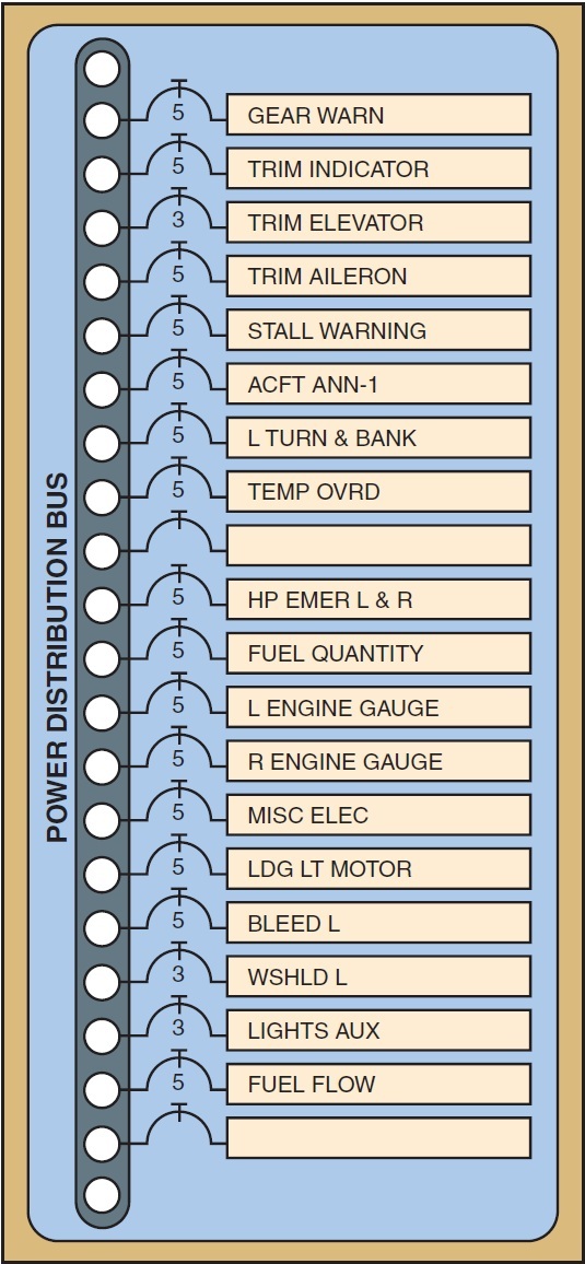
14-8The distribution of DC and AC power throughout the system is accomplished through the use of power distribution buses. These “buses” as they are called are actually common terminals from which individual electrical circuits get their power. [Figure 14-9]

Figure 14-9. Typical individual power distribution bus.
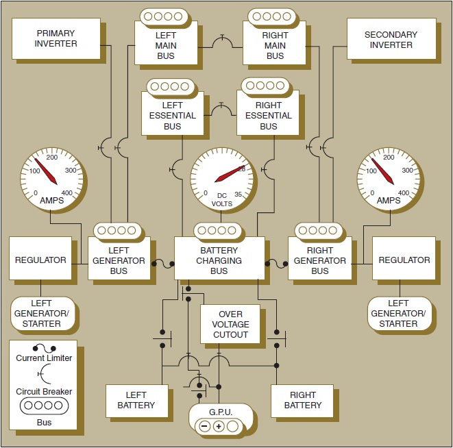
Buses are usually named for what they power (avionics bus, for example), or for where they get their power (right generator bus, battery bus). The distribution of DC and AC power is often divided into functional groups (buses) that give priority to certain equipment during normal and emergency operations. Main buses serve most of the airplane’s electrical equipment. Essential buses feed power to equipment having top priority. [Figure 14-10]
Multiengine turboprop airplanes normally have several power sources—a battery and at least one generator per engine. The electrical systems are usually designed so that any bus can be energized by any of the power sources. For example, a typical system might have a right and left generator buses powered normally by the right and left engine-driven generators. These buses will be connected by a normally open switch, which isolates them from each other. If one generator fails, power will be lost to its bus, but power can be restored to that bus by closing a bus tie switch. Closing this switch connects the buses and allows the operating generator to power both.
Power distribution buses are protected from short circuits and other malfunctions by a type of fuse called a current limiter. In the case of excessive current supplied by any power source, the current limiter will open the circuit and thereby isolate that power source and allow the affected bus to become separated from the system. The other buses will continue to operate normally. Individual electrical components are connected to the buses through circuit breakers.A circuit breaker is a device which opens an electrical circuit when an excess amount of current flows.

Figure 14-10. Simplified schematic of turboprop airplane electrical system.
PED Publication