Chapter 2—Ground Operations
Table of Contents
Visual Inspection
Inside the Cockpit
Outer Wing Surfaces and Tail Section
Fuel and Oil
Landing Gear, Tires, and Brakes
Engine and Propeller
Cockpit Management
Ground Operations
Engine Starting
Hand Propping
Taxiing
Before Takeoff Check
After Landing
Clear of Runway
Parking
Engine Shutdown
Postflight
Securing and Servicing

INSIDE THE COCKPIT
The inspection should start with the cabin door. If the door is hard to open or close, or if the carpeting or seats are wet from a recent rain, there is a good chance that the door, fuselage, or both are misaligned. This may be a sign of structural damage.
The windshield and side windows should be examined for cracks and/or crazing. Crazing is the first stage of delamination of the plastic. Crazing decreases visibility, and a severely crazed window can result in near zero visibility due to light refraction at certain angles to the sun.
The pilot should check the seats, seat rails, and seat belt attach points for wear, cracks, and serviceability. The seat rail holes where the seat lock pins fit should also be inspected. The holes should be round and not oval. The pin and seat rail grips should also be checked for wear and serviceability.

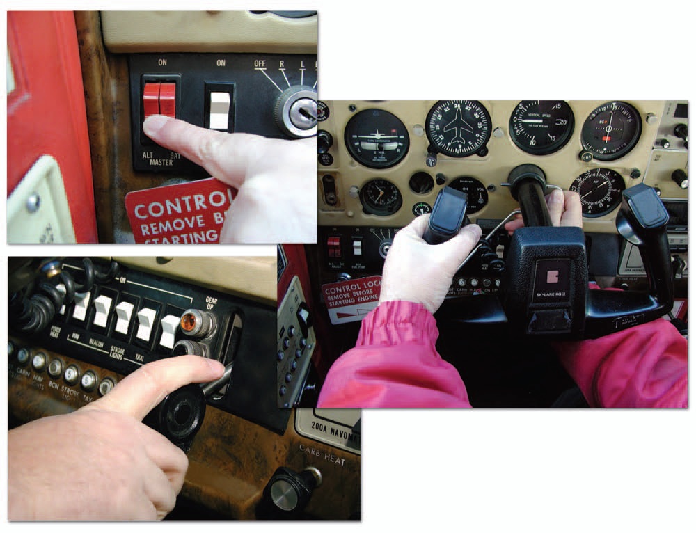
Figure 2-3. Inside the cockpit.
Inside the cockpit, three key items to be checked are:
- battery and ignition switches—off,
- control column locks—removed,
- landing gear control—down and locked.

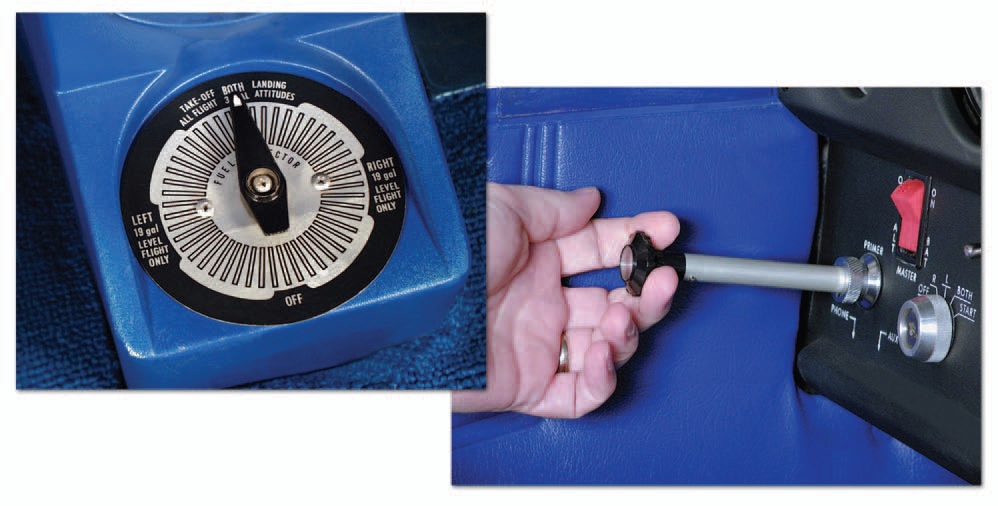
Figure 2-4. Fuel selector and primer.
The fuel selectors should be checked for proper operation in all positions—including the OFF position. Stiff selectors, or ones where the tank position is hard to find, are unacceptable. The primer should also be exercised. The pilot should feel resistance when the primer is both pulled out and pushed in. The primer should also lock securely. Faulty primers can interfere with proper engine operation. [Figure 2-4] The engine controls should also be manipulated by slowly moving each through its full range to check for binding or stiffness.
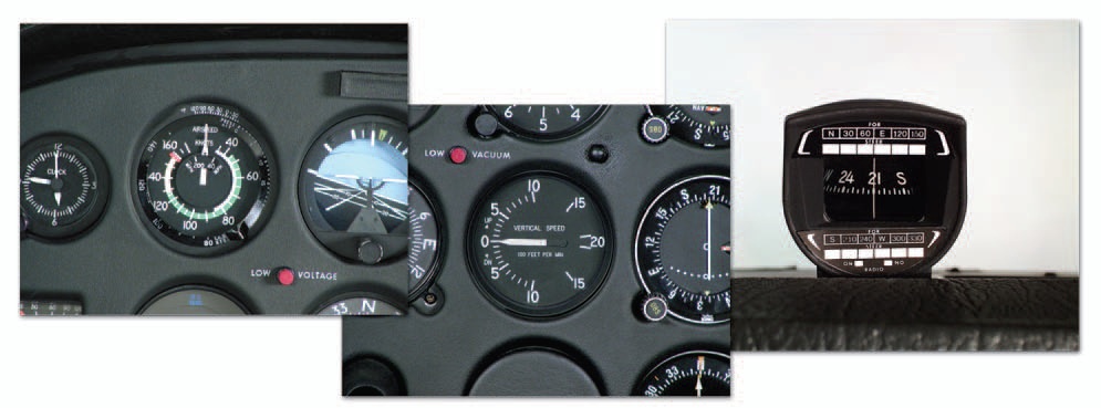
The airspeed indicator should be properly marked, and the indicator needle should read zero. If it does not, the instrument may not be calibrated correctly. Similarly, the vertical speed indicator (VSI) should also read zero when the airplane is on the ground. If it does not, a small screwdriver can be used to zero the instrument. The VSI is the only flight instrument that a pilot has the prerogative to adjust. All others must be adjusted by an FAA certificated repairman or mechanic.
The magnetic compass is a required instrument for both VFR and IFR flight. It must be securely mounted, with a correction card in place. The instrument face must be clear and the instrument case full of fluid. A cloudy instrument face, bubbles in the fluid, or a partially filled case renders the instrument unusable. [Figure 2-5]

Figure 2-5. Airspeed indicator, VSI, and magnetic compass.
The gyro driven attitude indicator should be checked before being powered. A white haze on the inside of

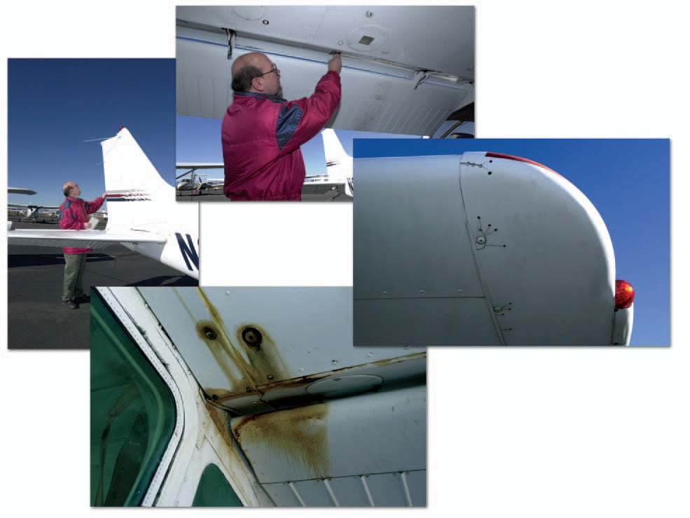
Figure 2-6. Wing and tail section inspection.
the glass face may be a sign that the seal has been breached, allowing moisture and dirt to be sucked into the instrument.
The altimeter should be checked against the ramp or field elevation after setting in the barometric pressure. If the variation between the known field elevation and the altimeter indication is more than 75 feet, its accuracy is questionable.
The pilot should turn on the battery master switch and make note of the fuel quantity gauge indications for comparison with an actual visual inspection of the fuel tanks during the exterior inspection.
PED Publication